
August 05, 2026
Quality Indicators for BIM Information Governance in Transportation Infrastructure
José Vinícius Silva Martins; Suranny Jiménez Chacón
DOI: 10.22167/2675-6528-202601003
Article prepared by the ResumeAI tool, an artificial intelligence solution developed by the Pecege Institute focused on synthesis and writing.
Abstract
The adoption of Building Information Modeling (BIM) in transportation infrastructure projects has expanded the possibilities for information integration throughout the lifecycle of the developments, but it has also highlighted challenges related to the quality and interoperability of data present in digital models. In this context, the objective was to develop a framework of performance indicators and objective audit criteria to evaluate the informational conformity and maturity of BIM models applied to transportation infrastructure. The research was characterized as applied, with a mixed approach and a design based on multiple case studies, involving two projects in the executive design phase, one road and one rail. Initially, a literature review and documentary analysis of contractual requirements were carried out, including EIR, BEP, and Level of Information Need, in light of the PMBOK and ABNT NBR ISO 19650 series references. Subsequently, BIM models in IFC 4.3 format were subjected to informational audit through rules structured in Information Delivery Specification (IDS), verified in an openBIM environment. The results showed recurring failures mainly associated with the absence or inconsistency of mandatory attributes and interoperability limitations between platforms. Based on these findings, quantitative indicators were structured to measure different dimensions of the informational quality of the models, contributing to strengthening BIM information governance and supporting quality control in infrastructure projects.
Keywords: BIM; Infrastructure; Information; Quality; Transport.
1. Introduction
The implementation of Building Information Modeling (BIM) represents a paradigm shift in project management within the Architecture, Engineering, and Construction (AEC) sector, especially in complex ventures such as transportation infrastructure. The ability to create and manage digital representations of an asset’s physical and functional characteristics enhances interdisciplinary collaboration, conflict detection, schedule and cost optimization, and infrastructure lifecycle management. In linear projects, like highways and railways, BIM also facilitates the integration of geospatial, geotechnical, and design data, providing a more comprehensive view for decision-making (Costin et al., 2018; Zhao et al., 2019).
Despite these benefits, the effectiveness of BIM is directly related to the quality and governance of the information managed in digital models (Song et al., 2017). The intensification of its use in infrastructure projects has highlighted challenges related to the consistency, accuracy, completeness, and interoperability of data. The absence of clear standards and objective metrics to evaluate informational quality results in models with semantically poor or inconsistent information, compromising critical analyses such as quantities, budgets, and construction planning (Tomczak et al., 2024).
Furthermore, even with the adoption of open formats such as Industry Foundation Classes (IFC) (ABNT, 2023), difficulties still persist in the fluid exchange of information between different platforms and agents involved in the project (Xu et al., 2018). This reality points to a practical and theoretical gap in ensuring the reliability and usability of BIM data throughout the project lifecycle, impacting decision-making and operational efficiency.
In this context, the quality of BIM information becomes a relevant aspect for the reliability of models and for meeting the intended uses in transportation infrastructure projects. The theoretical foundation of this work is based on four complementary pillars. ABNT NBR ISO 19650 (ABNT, 2022) guides information management throughout the asset’s lifecycle, establishing a framework for collaboration and information exchange. IFC 4.3 acts as an openBIM standard for data exchange and preservation between different platforms, aiming for interoperability and longevity of digital information.
The Information Delivery Specification (IDS) (buildingSMART International, 2025a) allows for the transformation of informational requirements into automatically verifiable rules, which is crucial for audit automation. The PMBOK (PMI, 2017), in turn, provides the logic for planning, managing, and controlling quality, integrating project management practices into the BIM information context. These references allow for the articulation of informational requirements, interoperability, and quality management, establishing the conceptual basis for transforming normative and contractual demands into verifiable audit criteria, justifying the need for a systematic approach to quality assessment.
Given the growing complexity of infrastructure projects and the need to ensure the reliability of digital models, the general objective of this work is to propose a framework of technical and managerial indicators to assess the informational compliance and maturity of BIM models applied to transportation infrastructure projects. The proposal seeks to convert informational requirements into metrics applicable to auditing, quality control, and BIM information governance, contributing to support technical and managerial decisions in infrastructure projects.
2. Material and Methods
The research is characterized as applied, aiming to solve a practical problem in the management of information quality in transportation infrastructure projects that use Building Information Modeling (BIM). A mixed approach was adopted, with qualitative and quantitative phases. The qualitative phase involved the interpretation of normative requirements and documentary analysis of project artifacts, while the quantitative phase focused on the proposal of measurable performance and compliance indicators. Regarding objectives, the research had an exploratory character, by proposing a new structure of indicators, and descriptive, by characterizing informational quality failures in case studies.
The main design was a multiple case study, focused on two transport infrastructure projects (one road and one rail), both developed in BIM. Data collection included a literature review, based on PMBOK (PMI, 2017), ABNT NBR ISO 19650 (ABNT, 2022), and openBIM standards (IFC ABNT, 2023; IDS buildingSMART International, 2025a). Complementarily, documentary research was carried out on artifacts such as the BIM Execution Plan (BEP), Exchange Information Requirements (EIR), contractor information exchange requirements, and BIM models in IFC 4.3 format (buildingSMART International, 2025b).
For the empirical evaluation of informational quality, two representative cases provided by the multinational Egis Group were selected, both in the executive design phase: a road development (section of a duplicated federal highway with an overpass intersection) and a railway development (interconnection between a railway yard and an iron plant). This selection aimed to cover typological, disciplinary, and technological diversity, reflecting real scenarios of linear projects. The road and railway models analyzed are presented in Figure 1 and Figure 2, respectively.
Figure 1. Federated model of the road project in Navisworks Manage
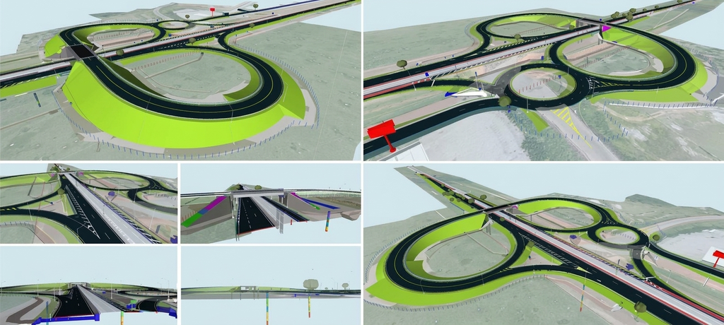
Figure 2. Federated model of the railway in Navisworks Manage
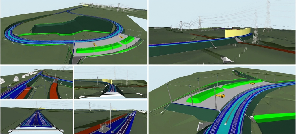
The models included linear infrastructure disciplines such as geometry, earthworks, paving, drainage, special structures (OAE), permanent way, signaling, retaining walls, and interferences. They were developed in various BIM software and exported to the IFC 4.3 format, an openBIM standard. This diversity allowed for the evaluation of the quality of the modeled information and failures in export, interoperability, and semantic consistency.
Table 1 details the technical characterization of the projects, including infrastructure type, disciplines, exchange formats, IFC standard, and BIM uses foreseen in the contractual EIR and BEP. The intentional choice of road and railway ventures, with distinct technical contexts, aimed to identify informational failure patterns in real BIM development environments, without the purpose of statistical generalization, and to substantiate the informational audit protocol.
Table 1. Technical characterization of the projects analyzed in the multiple case study
| Infrastructure type | of included Disciplines | Exchange format | of IFC Standard | Computer program | Main BIM uses foreseen in the EIR and BEP |
|---|---|---|---|---|---|
| Road | Linear infrastructure: geometry, earthworks, paving, drainage, signage and safety devices, topography, landscaping, retaining structures, interferences, complementary works, geotechnics and lighting | DWG/NWC/IFC | IFC 4.3 | Civil 3D | Modeling of existing conditions, authorial design, code validation |
| Road | Geology: soundings, water level and geological layers | IFC/NWC | IFC 4.3 | Leapfrog Works | Geological analyses (input to the BIM process) |
| Road | Special Works of Art (SWA): viaducts | RVT/NWC/IFC | IFC 4.3 | Revit | Modeling of existing conditions, authorial design, code validation |
| Railway | Linear infrastructure: permanent way (rails, sleepers, ballast), railway geometry, earthworks, drainage, signaling and safety devices, topography, landscaping, retaining structures, interferences, complementary works, geotechnics and lighting | DWG/NWC/IFC | IFC 4.3 | Civil 3D | Modeling of existing conditions, authorial design, code validation |
| Railway | Geology: soundings, water level and geological layers | DWG/NWC/IFC | IFC 4.3 | Leapfrog Works | Geological analyses (input to the BIM process) |
| Railway | Special Works of Art (SWA): bridges, viaducts, underpasses and overpasses | RVT/NWC/IFC | IFC 4.3 | Revit | Modeling of existing conditions, authorial design, code validation |
| Road and Rail | BIM Coordination: coordination and federated models | NWF/NWD | Navisworks Manage | 3D spatial coordination | |
| Road and Rail | Budget | elFC/IFC | IFC 4.3 | AltoQi Visus | Quantity extraction and cost estimation |
Note: In the present study, the term code validation refers to the verification of contractual requirements defined in the EIR and BEP, such as codes of the construction information classification system adopted in the contracts, not being restricted to automated regulatory validations
3. Results and Discussion
Information governance and quality management in BIM infrastructure projects
The literature on BIM applied to transportation infrastructure shows that the benefits of multidisciplinary coordination, reliability of quantities, and decision-making support directly depend on the quality and structuring of information in digital models. In linear projects, such as highways and railways, the integration of geometric, geospatial, and semantic data requires well-defined informational requirements to avoid inconsistencies throughout the asset’s lifecycle (Costin et al., 2018; Zhao et al., 2019). In this context, information governance plays a central role in ensuring that BIM models meet analytical, managerial, and operational demands.
Based on ABNT NBR ISO 19650, the definition of these requirements occurs through the formalization of the client’s needs in documents such as the EIR and the BEP, which establish responsibilities, formats, acceptance criteria, and required information levels. The concept of Level of Information Need (LoIN) complements this process by objectively specifying the geometric, alphanumeric, and documentary requirements by phase and purpose (ABNT, 2022; ISO, 2024). The systematization of these requirements was organized by lifecycle phase, responsible actor, and delivery type, as presented in Table 2, allowing normative guidelines to be converted into verifiable operational criteria.
Table 2. Matrix of informational requirements according to ABNT (2022) and ISO (2024)
| Phase | Responsible | Delivery type | Geometric requirements | Alphanumeric requirements | Documental requirements | Verification criterion |
|---|---|---|---|---|---|---|
| Conceptual project | Geometric designer | Models | Axis, grade, corridors, and typical sections | Segment identifier, functional class | Descriptive memorial | Geometric presence and minimum attributes |
| Executive project | Technical disciplines (OAE, drainage, paving, among others) | Models and data | Detailed geometry of elements | Complete property sets, classification, materials | Technical reports | Percentage of mandatory attributes filled |
| Construction | Builder | As-built models | As-built geometry | Quantities, service codes, status | Construction reports | Quantitative consistency × budget |
| Operation/maintenance | Operator | Asset database/model | Asset representative geometry | Unique identifier, lifespan, maintenance plan | Asset manual | Data integrity and traceability |
| All | BIM Manager | Reports/documents | BEP, validation records, IDS reports | Documental compliance |
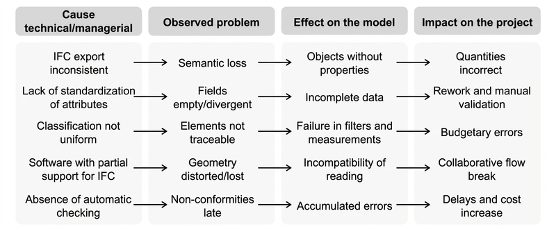
However, the literature on openBIM interoperability shows that the mere adoption of the IFC format does not guarantee informational quality or semantic consistency. Recurring problems include loss of meaning during export, absence of mandatory attributes, inconsistent use of classifications, and software compatibility limitations (Xu et al., 2018; Costin et al., 2018). These challenges were synthesized in the cause-problem-effect-impact chain presented in Figure 3, highlighting that interoperability constitutes both a technical and a managerial challenge. In response, standards such as IFC 4.3 and IDS have been proposed to structure requirements in a machine-auditable format, contributing to the reduction of inconsistencies (buildingSMART International, 2025a; Tomczak et al., 2024).
Figure 3. Cause–problem–effect–impact chain of openBIM interoperability challenges in infrastructure projects according to Xu et al. (2018) and Costin et al. (2018)
From the consolidation of these normative and theoretical references, a systematized classification of recurring informational failures was structured, organized according to information quality dimensions, such as completeness, consistency, accuracy, semantic conformity, and interoperability, as presented in Table 3. This classification allows associating each type of deviation with its potential causes and impacts, connecting contractual requirements and interoperability challenges to objective evaluation criteria.
Table 3. Classification of recurrent informational failures in BIM infrastructure models, based on Song et al. (2017), Xu et al. (2018), ABNT (2022) and Tomczak et al. (2024)
| Quality dimension | Definition | Practical examples | Detection method |
|---|---|---|---|
| Completeness | Mandatory information present | Empty property sets, absence of material | IDS Rule: mandatory attribute |
| Consistency | Nomenclature/structure standardization | Different names for the same element | Leaderboard check |
| Accuracy | Correspondence with reality/project | Incorrect volumes, wrong quotas | Model X reference comparison |
| Semantic compliance | Correct use of IFC classes | IfcBuildingElementProxy undue | IFC schema validator |
| Interoperability | Interoperability between software | Data loss on import | Pre and post-export comparison |
However, the definition of requirements and the identification of technical challenges, in isolation, do not ensure the quality of the process. To be effective, these requirements need to be systematically planned, monitored, and verified. In this sense, project quality management offers a framework for structuring BIM information governance, by bringing together the processes of planning, managing, and controlling quality with the practices of digital information management (PMI, 2017; ABNT, 2022).
In planning, this relationship appears in the definition of informational requirements and acceptance criteria, such as EIR, BEP, LoIN, and IDS. In execution, it manifests in interdisciplinary coordination and continuous model validations. In control, it occurs through rule-based audits, indicators, and traceable evidence. This equivalence is synthesized in Table 4, which relates PMBOK processes to BIM information governance activities.
Table 4. Correlation matrix between PMBOK quality processes and BIM information governance activities, based on PMI (2017) and ABNT (2022)
| PMBOK Process | Process objective | Equivalent in BIM governance | Practical examples |
|---|---|---|---|
| Plan Quality | Define criteria and standards | EIR, BEP, LoIN, IDS | Attribute requirements, classification, acceptance criteria |
| Quality Management | Ensure execution as planned | BIM Coordination, internal validations, model reviews | Clash detection, property checking, standardization |
| Quality Control | Verify conformity of deliverables | IFC/IDS Audit, records, KPIs | Percentage of filled attributes, non-conformity reports |
The flow presented in Figure 4 represents the sequence of activities that integrates modeling, interdisciplinary coordination, and successive checks before formal deliveries. This structure highlights that the reliability of the models depends on the articulation between production and intermediate checks, preventing the accumulation of inconsistencies. Figure 5 complements this approach by applying the PDCA cycle to the BIM context, relating requirements definition, execution, verification through rule-based audits, and adjustments resulting from the obtained outcomes. The integration between operational flow and continuous improvement sustains the systematic control of deliveries and the evolution of model maturity throughout the project.
Figure 4. Operational flow of execution, coordination, and continuous validations during the production of BIM models, based on PMI (2017), ABNT (2022), and Song et al. (2017)
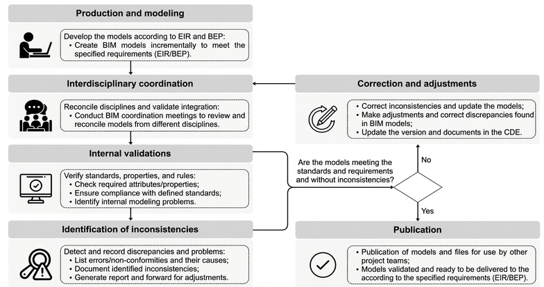
Figure 5. Application of the PDCA cycle to BIM information quality control, based on PMI (2017), ABNT (2022) and buildingSMART International (2025a)
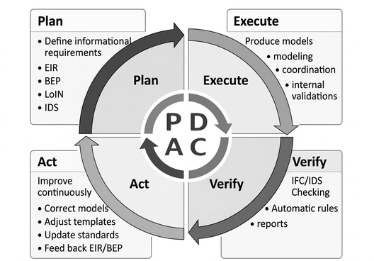
As an integrative synthesis, the results indicate that BIM information governance can be structured coherently with the quality management processes of PMBOK. The definition of requirements corresponds to quality planning; the production of models and interdisciplinary coordination relate to quality management; and rule-based audits, indicators, and traceable evidence configure quality control. This articulation supports the continuous improvement of models and reinforces the application of project management references to the context of digital information.
This integration between normative requirements, interoperability, and quality management establishes the conceptual basis for the empirical stage of the research. The following section applies these principles to the analysis of road and rail infrastructure BIM models, seeking to identify, classify, and quantify recurring informational failures in a multiple case study.
Identification of informational failures in BIM models through a multiple case study
The empirical application of the discussed frameworks was carried out through a multiple case study involving two transport infrastructure ventures, one road and one rail, both in the executive design phase. The case studies included a road venture (a section of a duplicated federal highway with a grade-separated intersection) and a rail venture (interconnection between a rail yard and an iron plant), both provided by the multinational company Egis Group. The models cover typical linear infrastructure disciplines, such as geometry, earthworks, paving, drainage, special structures (OAE), permanent way, signaling, retaining structures, and interferences, developed in different BIM authoring software and exported to the IFC 4.3 format as an openBIM exchange standard. The analysis started from the information requirements defined in the respective contractual EIR and BEP, which specified mandatory attributes, classification criteria, modeling responsibilities, and planned BIM uses, such as quantification and interdisciplinary coordination. These documents served as the basis for defining the scope of the information audit and for verifying the adherence between what was contractually requested and what was effectively delivered in the models.
The analyzed elements were organized according to the life cycle phase, the actors involved, and the type of delivery contractually foreseen. The LoIN was operationalized by objectively explicating the attributes and documents required by discipline and purpose of use, avoiding generic classifications of detail level. Table 5 presents a synthesis of these parameters, structured into transversal and technical properties. This systematization allowed contractual requirements to be transformed into verifiable audit criteria, in coherence with the governance approach discussed previously.
Table 5. Synthesis of the informational requirements of BIM objects for linear infrastructure projects
| BIM Objects | Code | Name | Discipline | Length | Width | Height | Thickness | Field | Quantity | Diameter | Weight |
|---|---|---|---|---|---|---|---|---|---|---|---|
| Digital Terrain Model (DTM) | X | X | X | X | |||||||
| Surveys | X | X | X | X | |||||||
| Geological layers | X | X | X | ||||||||
| Water level | X | X | X | ||||||||
| Alignments | X | X | X | X | |||||||
| Collection boxes, connection, passage | X | X | X | X | X | ||||||
| Curb, gutters, ditches, drains, channels | X | X | X | X | X | ||||||
| Water descents | X | X | X | X | X | ||||||
| Energy dissipators | X | X | X | X | |||||||
| Manholes | X | X | X | X | X | ||||||
| Manholes | X | X | X | X | |||||||
| Trenches | X | X | X | X | |||||||
| Cuts, fills, CFT, reinforcements, loans, deposits (earthworks) | X | X | X | X | |||||||
| Clearing (earthworks) | X | X | X | X | X | X | |||||
| Asphalt layers | X | X | X | X | X | X | X | X | |||
| Base, sub-base, subgrade, rigid, pavement and other coverings | X | X | X | X | X | X | X | ||||
| Asphalt primer | X | X | X | X | |||||||
| Bonding paint | X | X | X | X | |||||||
| Rails | X | X | X | X | |||||||
| Concrete sleepers, wood | X | X | X | X | X | X | |||||
| Ballast and sub-ballast | X | X | X | X | X | X | |||||
| Mudguard | X | X | X | X | |||||||
| AMV and bumper | X | X | X | ||||||||
| Brake shoe | X | X | X | X | |||||||
| Drainage geocomposite | X | X | X | X | |||||||
| Gabion, terramesh-system, terrameshgreen | X | X | X | X | X | X | |||||
| Modular concrete facing (geotechnical containment) | X | X | X | X | X | ||||||
| Geosynthetic | X | X | X | X | |||||||
| Geotechnical ties and drains | X | X | X | X | X | X | |||||
| Concrete facing (geotechnical containment) | X | X | X | X | X | X | |||||
| Vertical and horizontal signage | X | X | X | X | |||||||
| Road safety barriers and defenses | X | X | X | X | |||||||
| License plate supports and energy absorbing terminals | X | X | X | X | |||||||
| Guardrails, fences and designed walls | X | X | X | X | |||||||
| Vegetation cover (landscaping) | X | X | X | X | |||||||
| Areas subject to expropriation | X | X | X | X | X | ||||||
| Limits (domain range) | X | X | X | X | |||||||
| Existing fences and walls | X | X | X | X | |||||||
| Existing trees | X | X | X | X | |||||||
| Existing poles, forests, roads, railways, and high-voltage towers | X | X | X | X | |||||||
| Existing tours | X | X | X | X | X | X | |||||
| Existing buildings | X | X | X | X | |||||||
| Lighting cables | X | X | X | X | |||||||
| Lighting post | X | X | X |
Note: The properties were presented without the use of special characters, such as spaces and accents, in order to preserve syntactic compatibility and avoid inconsistencies in export, validation, and interoperability processes in an openBIM environment
Table 5 presents a summary of the informational requirements for BIM objects in linear infrastructures, structured into cross-cutting properties linked to the Work Breakdown Structure (WBS) and specific technical properties by element type. For Special Works (Obras de Arte Especiais – OAE) objects, the requirements followed the same structuring logic, including elements such as foundation blocks, footings, piles, columns, beams, decks, transition slabs, retaining walls, abutments, waterproofing, bearings, corbels, expansion joints, and guardrails. In addition to cross-cutting identification properties, such as code, name, and discipline, technical attributes associated with the geometric and quantitative characterization of these elements were considered, including length, width, height, thickness, shape area, volume, diameter, and weights of active and passive steel. This systematization allowed contractual requirements to be transformed into verifiable audit criteria, in coherence with the governance approach discussed previously.
From a technical point of view, the original models were produced in different authoring software and subsequently exported to the IFC 4.3 format, adopted as the openBIM exchange standard. A mapping of the IFC properties (Table 6) and entities (Table 7 and Table 8) used by discipline was performed, focusing on the correspondence between classes expected in the schema and the elements effectively exported. During this stage, recurring difficulties were identified related to inconsistent property export, use of generic classes, and loss of alphanumeric information, highlighting challenges already pointed out in the literature on semantic interoperability (Xu et al., 2018; Costin et al., 2018). These findings reinforce the premise that interoperability depends not only on the adoption of the IFC format but also on the correct structuring and validation of data.
Table 6. Mapping of IFC properties in BIM objects of the projects
| Property Set | IFC Parameter | Units of measure | Data Type |
| EAP | Code | – | IfcIdentifier |
| Name | – | IfcLabel | |
| Discipline | – | IfcLabel | |
| [Project Phase]_[Discipline]_[Object] Examples: Exe_DRE_Manhole Exe_OAE_Beam | Length Width | m m | IfcLengthMeasure IfcReal |
| Height | m | IfcReal | |
| Thickness | m | IfcReal | |
| Field | m² | IfcAreaMeasure | |
| Quantity | m³ | IfcVolumeMeasure | |
| Diameter | m | IfcReal | |
| Weight | t | IfcReal | |
| Form Area | m² | IfcAreaMeasure | |
| ActiveWeight | kg | IfcReal | |
| PassiveSteelWeight | kg | IfcReal |
Table 7. IFC Mapping of BIM Objects from Linear Infrastructure Projects
| Project Discipline | BIM Objects | IFC Class (IfcClass) | PredefinedType (PredefinedType) | ObjectType |
|---|---|---|---|---|
| Topography (TOP) | Digital Terrain Model (DTM) | IfcGeographicElement | LAND | |
| Topography (TOP) or Interference Survey (CAD) | Fences | IfcRailing | Barrier | |
| Topography (TOP) or Interference Survey (CAD) | Walls | IfcWall | ||
| Topography (TOP) or Interference Survey (CAD) | Trees, forests | IfcGeographicElement | PLANT LIFE | |
| Topography (TOP) or Interference Survey (CAD) | Poles with luminaires | IfcLightFixture | SOURCE DIRECTION | |
| Topography (TOP) or Interference Survey (CAD) | Routes | IfcRoad | ||
| Topography (TOP) or Interference Survey (CAD) | Railways | IfcRailway | ||
| Topography (TOP) or Interference Survey (CAD) | High-voltage power lines | IfcElementAssembly | TRUSS | |
| Topography (TOP) or Interference Survey (CAD) | Tours | IfcSlab | Pavement | |
| Topography (TOP) or Interference Survey (CAD) | Buildings | IfcBuilding | ||
| Topography (TOP) or Interference Survey (CAD) | Surveys | IfcBorehole | ||
| Geology (GEG) | Geological layers | IfcGeotechnicalStratum | Robust | |
| Geology (GEG) | Water level | IfcGeotechnicalStratum | H2O | |
| Geometry (GEO) | Alignments | IfcAlignment | ||
| Drainage (DRE) | Collection boxes | IfcDistributionChamberElement | SUMP | |
| Drainage (DRE) | Junction boxes, pass-through and inspection boxes | IfcDistributionChamberElement | Maintenance hole | |
| Drainage (DRE) | Curb | IfcKerb | ||
| Drainage (DRE) | Gutters, drains and ditches | IfcPipeSegment | Inner Margin | |
| Drainage (DRE) | Drains | IfcFlowSegment | USERDEFINED | Drainage |
| Drainage (DRE) | Water descents | IfcFlowSegment | USERDEFINED | Leader |
| Drainage (DRE) | Energy dissipators | IfcFlowTerminal | USERDEFINED | Energy_Dissipator |
| Drainage (DRE) | Manholes | IfcPipeSegment | Drainage conduit | |
| Drainage (DRE) | Manholes | IfcWall | EARTH-RETAINING STRUCTURE | |
| Earthworks (TER) | Cuts | IfcEarthworksCut | CUT | |
| Earthworks (TER) | Landfills | IfcEarthworksFill | DIKE | |
| Earthworks (TER) | Final earthworks layer (FEL) | IfcEarthworksFill | Transition Section | |
| Earthworks (TER) | Subgrade reinforcement | IfcEarthworksFill | SUBGRADEBED | |
| Earthworks (TER) | Pavement demolition | IfcEarthworksCut | PAVEMENT MILLING | |
| Earthworks (TER) | Cleaning | IfcEarthworksCut | TOPSOILREMOVAL | |
| Paving (PAV) | Asphalt layers, Asphalt priming, tack coat, base, sub-base, rigid, other pavements | IfcCourse | Pavement | |
| Permanent way – railway superstructure (SUF) | Tours | IfcSlab | Pavement | |
| Permanent way – railway superstructure (SUF) | Rails | IfcRail | TRACK | |
| Permanent way – railway superstructure (SUF) | Concrete and wooden sleepers | IfcTrackElement | SLEEPER | |
| Permanent way – railway superstructure (SUF) | Ballast | IfcCourse | BALLAST BED | |
| Permanent way – railway superstructure (SUF) | Sub-base | IfcCourse | USERDEFINED | Sub-ballast |
| Permanent way – railway superstructure (SUF) | Mudguard | IfcWall | EARTH-RETAINING STRUCTURE | |
| Permanent way – railway superstructure (SUF) | AMV | IfcTrackElement | ||
| Permanent way – railway superstructure (SUF) | Bumper | IfcTrackElement | VEHICLESTOP | |
| Permanent way – railway superstructure (SUF) | Brake shoe | IfcTrackElement | BLOCKINGDEVICE | |
| Geotechnics (GET) | Drainage geocomposite and geosynthetic | IfcCourse | Screen | |
| Geotechnics (GET) | Gabion, terramesh-system, terrameshverde and concrete facing | IfcWall | EARTH-RETAINING STRUCTURE | |
| Geotechnics (GET) | Tie Rods | IfcTendon | Component | |
| Geotechnics (GET) | Drains | IfcPipeSegment | RIGIDSEGMENT | |
| Signaling and Safety Devices (SDS) | Vertical signage | IfcElementAssembly | SIGNALASSEMBLY | |
| Signaling and Safety Devices (SDS) | Horizontal signage (chevrons/symbols) | IfcSurfaceFeature | PAVEMENT SURFACING MARKING | |
| Signaling and Safety Devices (SDS) | Horizontal signage (lines and edge markings) | IfcSurfaceFeature | MARKING OF LINES | |
| Signaling and Safety Devices (SDS) | Road safety barriers and defenses | IfcRailing | Safety barrier | |
| Complementary Works (OBC) | Fences | IfcRailing | Barrier | |
| Complementary Works (OBC) | Guardrail | IfcRailing | Safety barrier | |
| Complementary Works (OBC) | Walls | IfcWall | ||
| Complementary Works (OBC) | Vegetation cover (landscaping) | IfcGeographicElement | PLANT LIFE | |
| Expropriation (DES) | Areas subject to expropriation | IfcSpatialZone | USERDEFINED | Expropriation Area |
| Expropriation (DES) | Limits (domain range) | IfcSpatialZone | USERDEFINED | Administrative Boundary |
| Lighting (ILU) | Lighting cables | IfcCableSegment | CABLESEGMENT | |
| Lighting (ILU) | Post with luminaires | IfcLightFixture | SOURCE DIRECTION |
Table 8. IFC Mapping of BIM Objects from OAE Projects
| Project Discipline | BIM Objects | IFC Class (IfcClass) | PredefinedType | Object type (ObjectType) |
| Special Works of Art (SWA) | Foundation blocks and footings | IfcBridgePart | FOUNDATION | |
| Concrete piles | IfcPile | – | ||
| Concrete columns | IfcColumn | – | ||
| Concrete beams | IfcBeam | – | ||
| Transition slabs and decks | IfcBridgePart | DECK_SEGMENT | ||
| Structural containments | IfcWall | EARTH-RETAINING STRUCTURE | ||
| Meetings | IfcBridgePart | PILLAR | ||
| Waterproofing | IfcCovering | MEMBRANE | ||
| Support devices | IfcDiscreteAccessory | USERDEFINED | SupportPoint | |
| Control panels | IfcDiscreteAccessory | square bracket | ||
| Expansion joints | IfcDiscreteAccessory | EXPANSION_JOINT_DEVICE | ||
| Guardrail | IfcRailing | Safety barrier |
The informational audit was based on the quality dimensions previously systematized and converted into verifiable criteria through IDS rules. Figure 6 presents an excerpt of the IDS structure in XML and its application in verifying models in Blender BIM (Bonsai), an open-source software based on the IfcOpenShell library, responsible for generating structured reports of non-conformities by model and discipline. Table 9 relates quality dimension, applied criterion, validation rule, and generated evidence, demonstrating how contractual requirements were translated into automated checks in the openBIM environment. This structure ensures traceability between the contractual LoIN, the IFC mapping, and the audit results, methodologically consolidating quality control.
Figure 6. Excerpt from the IDS structure in XML and audit of models in Blender BIM (Bonsai): IDS XML structure (A); road project pavement model (B); permanent way model – railway superstructure (C); road project OAE model (D); railway project OAE model (E)
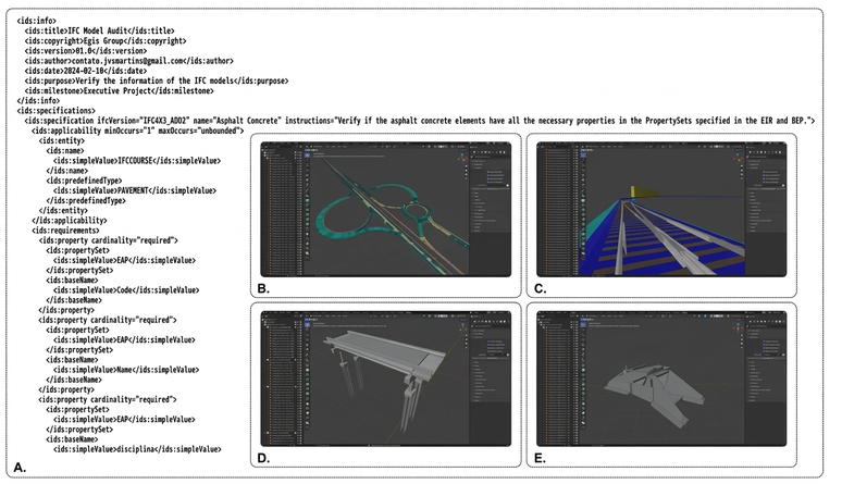
Table 9. Operationalization of informational quality dimensions in the audit of IFC models
| Quality dimension | Criterion applied | Operational validation rule | Audit-generated evidence |
|---|---|---|---|
| Completeness | Presence of mandatory attributes defined in the contractual LoIN | IDS: mandatory property (required) | Percentage of compliant elements and list of missing attributes |
| Consistency | Adherence to the nomenclature standardization and classification system defined in the contract | IDS: allowed value validation / divergent comparison with reference table discipline | List of divergent values by discipline |
| Accuracy | Coherence between modeled geometry and quantities predicted in technical documentation | Automated extraction of quantities and comparison with contractual reference | Percentage difference between model and baseline |
| Semantic compliance | Proper use of IFC PredefinedType classes | IDS: Entity and attribute validation classified according to IFC 4.3 schema | List of incorrectly classified entities |
| Interoperability | Maintaining integrity of IFC attributes export/import | Comparison of properties before and after IFC export and re-import | List of lost, changed, or inconsistent attributes |
The application of the rules to the road and rail models allowed for the objective quantification of the identified non-conformities, as presented in Table 10. The rail model presents a significantly larger number of analyzed elements, mainly due to the permanent way superstructure, with approximately 12,231 concrete sleepers individually modeled, which increases the total volume of evaluated objects and the absolute values of occurrences. However, when considering the percentage rates of non-conformity, similar behavior is observed between the two projects, indicating that the deviations do not arise solely from the scale of the models, but reflect structural patterns of governance and information control, reinforcing the need for systematic validations throughout production.
Table 10. Quantitative summary of non-conformities by model
| Model | Total elements analyzed | Total of non-conformities | Non-compliance rate (%) |
|---|---|---|---|
| Road | 6.777 | 1.565 | 23,09% |
| Railway | 16.847 | 4.389 | 26,05% |
The distribution of occurrences by discipline, presented in Figure 7, shows that certain areas concentrate a higher volume of inconsistencies, especially those associated with multiple technical attributes and strong dependence on standardization. This behavior confirms that informational quality in linear projects is directly related to the clarity of requirements and interdisciplinary coordination, in line with the interoperability challenges discussed. The heterogeneity observed between disciplines also demonstrates that informational maturity is not uniform within the same undertaking, an aspect relevant for comparative analyses and prioritization of corrective actions.
Figure 7. Recurrence of non-conformities by discipline and by project
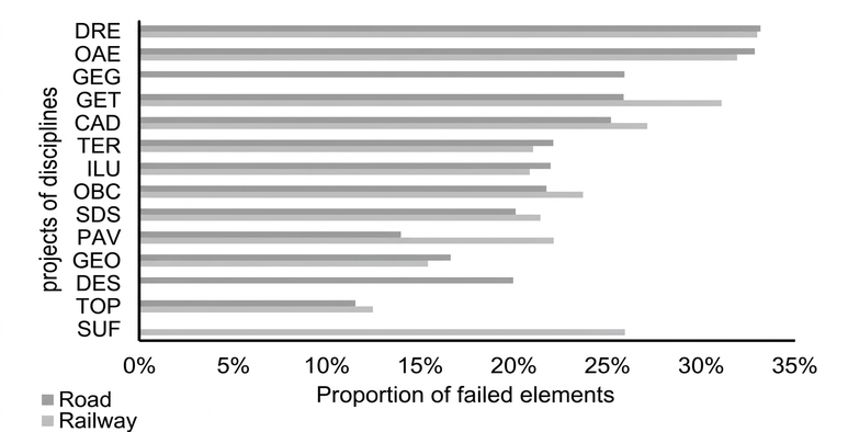
Note: The figure presents only the disciplines that registered non-conformities during the audit. Disciplines without failures were not represented in the graph
Finally, the Pareto Analysis presented in Figure 8 reveals a significant concentration of non-conformities in the dimensions of completeness and consistency, while geometric accuracy, semantic compliance, and interoperability show a lower relative incidence. The cumulative curve shows that a restricted set of failure types accounts for the largest share of identified deviations, allowing for the prioritization of interventions without yet characterizing them as performance indicators. This empirical consolidation constitutes the objective basis for the development, in the following section, of structured criteria for evaluating the conformity and informational maturity of BIM models.
Figure 8. Pareto analysis of non-conformities identified by information quality dimension in the analyzed BIM models
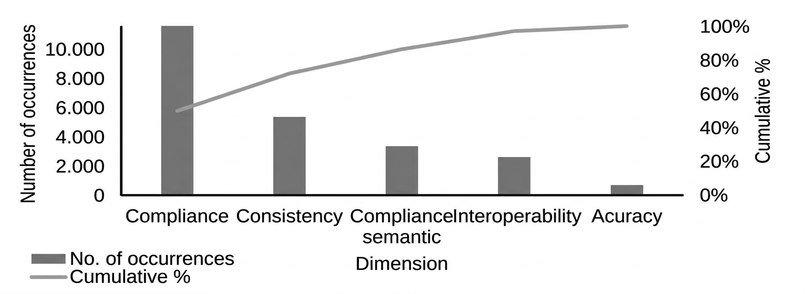
Note: Abbreviations used: Comp. (Completeness), Consist. (Consistency), Semantic Conf. (Semantic Conformity) and Interop. (Interoperability)
Performance indicators for assessing compliance and informational maturity in BIM
The consolidation of non-conformities identified in the multiple case study allowed for the structuring of quantitative performance indicators aimed at the objective measurement of the informational quality of BIM models. Derived from previously operationalized quality dimensions, these indicators transform audit results into comparable metrics throughout the project cycle, enabling systematic evaluation of informational compliance and maturity. The corresponding mathematical expressions are presented in forms (1) to (5).
The Informational Completeness Index (ICI) can be calculated by means of eq. (1):
ICI= AC/AO ×100 (1)
where: AC: is the number of conforming attributes; and AO: is the number of mandatory attributes.
The Intraclass Correlation Coefficient (ICC) can be calculated using eq. (2):
ICC = EC/EA ×100 (2)
where: EC: is the number of correctly classified elements; and EA: is the number of evaluated elements.
The Semantic Compliance Index IFC (ICS) can be calculated by means of eq. (3):
ICS = Eifc/ET ×100 (3)
where: Eifc: is the number of elements with the correct IFC class; and ET: is the total number of elements.
The Interoperability Integrity Index (III) can be calculated using eq. (4):
III = API/AO ×100 (4)
where: API: is the number of attributes preserved after exchange; and AO: is the number of original attributes.
The Quantitative Accuracy Index (QAI) can be calculated by means of eq. (5):
IAQ = (1 – |Qmodel – Qreference|/Qreference) ×100 (5)
where: Qmodel: is the quantity automatically extracted from the BIM model; Qreference: is the quantity foreseen in the memorial, technical spreadsheet, or contractual basis.
The CI, defined in form. (1), corresponds to the ratio between compliant attributes (AC) and mandatory attributes (AO), expressing the degree of compliance with the requirements established in the contractual LoIN. The ICC, presented in form. (2), relates the number of correctly classified elements (EC) to the total number of evaluated elements (EA), reflecting the structural standardization level of the model. The ICS, form. (3), measures the proportion of elements with an adequate IFC class (Eifc) in relation to the total number of elements (ET), ensuring adherence to the IFC 4.3 schema. The III, form. (4), evaluates the preservation of attributes after IFC exchange, relating preserved attributes (API) to original attributes (AO). Finally, the IAQ, form. (5), measures the proximity between the quantities extracted from the model (Qmodelo) and the technical reference values (Qreferência), indicating the degree of model reliability for cost estimates and analyses.
Together, these indicators allow for the evaluation of performance by discipline and by model, overcoming the isolated analysis of non-conformities and enabling the evolutionary monitoring of informational quality throughout the project development. The consolidation of results was carried out through Business Intelligence (BI) dashboards, where the indices are visualized in an integrated manner by project and by quality dimension, providing a broader and more structured managerial view. This approach makes it possible to identify variations between disciplines, recognize critical points, prioritize interventions, and support evidence-based decision-making. Figure 9 presents the BIM informational quality dashboard applied to the road project, exemplifying the operationalization of indicators and the use of BI as a tool for information monitoring and governance.
Figure 9. BIM information quality dashboard for highway project
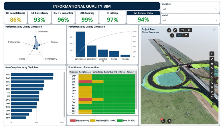
The practical effectiveness of the indicators was observed in meeting one of the main BIM uses contractually foreseen in the multiple case study: the extraction of quantities and cost estimates. After the improvement of the indices, mainly completeness and consistency, the models could be quantified in a structured way in AltoQi Visus (Figure 10). The use of the Codigo property as a unique identifier, linked to the WBS and cost compositions, enabled the generation of traceable estimates aligned with the contractual scope.
Figure 10. Extraction of quantities and cost estimation in AltoQi Visus from the BIM models of the railway project, linking properties to WBS codes and budget compositions
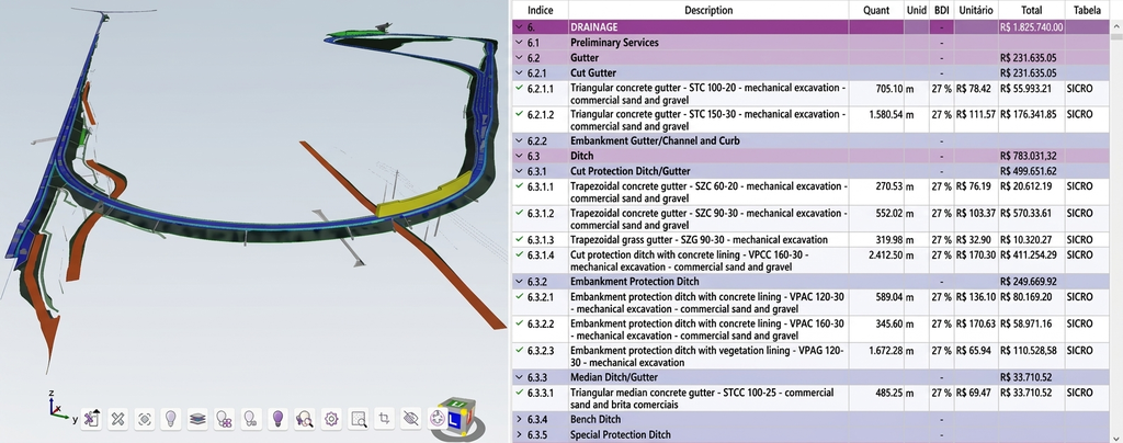
These results demonstrate that the proposed indicators are not limited to abstract metrics, but constitute operational instruments associated with the enablement of the foreseen BIM uses. The predominance of completeness and consistency failures reinforces that the adoption of IFC, in isolation, does not guarantee informational quality or full interoperability, requiring the prior definition of requirements, standardization of properties, and systematic validation of deliverables. The similarity between the percentage rates of non-conformity in road and rail projects suggests structural weaknesses in information governance processes, consolidating informational quality as a condition for value generation in infrastructure projects.
4. Conclusion
This work evidenced that the informational quality of BIM models is determinant for the reliability of information and for interoperability in transportation infrastructure projects. The case analysis demonstrated that inconsistencies in filling out properties, in element classification, and in data standardization compromise the use of models in analytical, managerial activities, and in contractual BIM uses, such as quantity extraction and cost estimations.
The articulation between informational requirements, BIM governance, and quality management allowed for the structuring of an approach to assess informational compliance. The audit structure and proposed indicators convert normative and contractual requirements into objective verification criteria. As a limitation, the application occurred in two case studies in the executive project phase and in a specific organizational context. As a future perspective, it is recommended to extend the proposal to other contexts, lifecycle phases, and common data environments.
Bibliographic References
Brazilian Association of Technical Standards [ABNT]. 2022. ABNT NBR ISO 19650 Series: Organization and digitalization of information about buildings and civil engineering works, including building information modeling (BIM) – Information management using building information modeling. Rio de Janeiro, May 27, 2022.
Brazilian Association of Technical Standards [ABNT]. 2023. ABNT NBR ISO 16739-1: Industry Foundation Classes (IFC) for the sharing of data by the construction and facility management industries – Part 1: Data schema. Rio de Janeiro, Dec. 29, 2023.
buildingSMART International. 2025a. IDS: Computer interpretable (XML) standard to define Information Delivery Specifications for BIM. Available at: . Accessed: 28 Oct. 2025.
buildingSMART International. 2025b. IFC 4.3.2 Documentation. Available at: . Accessed on: 28 Oct. 2025.
Costin, A.; Adibfar, A.; Hu, H.; Chen, S. 2018. Building Information Modeling (BIM) for transportation infrastructure – Literature review, applications, challenges, and recommendations. Automation in Construction 94: 257-281.
International Organization for Standardization [ISO]. 2024. ISO 7817-1:2024: Building information modelling – Level of information need – Part 1: Concepts and principles. Geneva, 19 Jun. 2024.
Project Management Institute [PMI]. 2017. A Guide to the Project Management Body of Knowledge. 6th ed. Project Management Institute, Newton Square, PA, USA.
Song, J.; Migliaccio. G.; Wang, G.; Lu, H. 2017. Exploring the Influence of System Quality, Information Quality, and External Service on BIM User Satisfaction. Journal of Management in Engineering 33 (6): 04017036.
Tomczak, A.; Benghi, C.; van Berlo, L.; Hjelseth, E. 2024. Requiring Circularity Data in BIM With Information Delivery Specification. Journal of Circular Economy 1(2): 1-13.
Xu, Z.; Huang, T.; Li, B.; Li, H.; Li Q. (2018). Developing an IFC-Based Database for Construction Quality Evaluation. Advances in Civil Engineering 2018(1): 1-22.
Zhao, L.; Liu, Z.; Mbachu, J. 2019. Highway Alignment Optimization: An Integrated BIM and GIS Approach. ISPRS International Journal of Geo-Information 8(4): 172.
Article originating from the Final Course Work of the Specialization in Project Management of the MBA USP/Esalq
To learn more about the course, click here and access the MBX Academy platform